Aussi, il semble qu'il soit possible de réaliser l'opération logiciellement.
cf:
FAQ for the firmware and BIOS Editor individual data cards ASUS P8xxx and ROG-analogues
Cette traduction auto vient d'origine d'1 site russe,
ici: rendez-vous dans la § 8 et dépliez les spoiler 8.1 et 8.2, puis rechargez la page pour que la traduction s'affiche correctement.
Ce qui donne (en anglais, la traduc° étant bien meilleure qu'en français):
8. Removal of protection from all regions of the BIOS firmware.
To protect against accidental or intentional damage to the regions was implemented Intel BIOS software mechanism lock access to them. But sometimes this protection prevents lifting a backup, or Altering of any region, so it must be switched off for a while or permanently.
There are several ways to remove this protection, I will describe each of them.
Intel refers to the two full-time decryption methods: hardware and software. Hardware associated with filing a logical unit to foot HDA_SDO chipset during lifting signal # PWROK, ie does during POST. The software associated with sending a special message for Management Engine, but the format of this message is not described anywhere and used such reports only of the Intel (in the FPT and MEUpdate, for example). Unfortunately, there is no publicly available tool that could send this message, so we can not programmatically accessible. If someone has such a utility - please share.
There is another way to remove this hardware protection, which was mentioned earlier in this FAQ. This removal of it by resetting the values in region lock the region descriptor with the programmer. Unlike the two previous methods, the protection is not lifted on time, and for good.
In fact, nothing prevents the first way to remove the protection hardware Intel, and then write the new value in the descriptor sequence region lock and leave protection removed.
I'll describe both of these methods in more detail.
8.1. Hardware deprotection
First let's look in the
datasheet for the 6 Series chipsets.
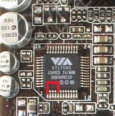
Intel and says that it is a signal HDA_SDO off protection. It remains to find exactly where it is displayed.
There may be two possibilities: on the boards with embedded audio, this conclusion has on one of the legs of a sound chip, and on the boards without onboard sound to be output separately on the jumper.
The second case I do not consider as Unprotect ME on server boards described in the documentation for them, is the first case.
First, let's clarify w-hat are "feeding the output of the logical unit HDA during lifting # PWROK": simple, it is just the closure of the line to line HDA_SDO 3.3 from the moment the PC until the POST process image on the screen (take a bit with the stock , but it is easier to navigate.)
It remains to find these same HDA_SDO and 3.3 V. It is very easy: since HD Audio chip layout is standardized, it will always be HDA_SDO № 5 foot, and the nearest convenient foot 3.3 - № 1.
If you want to verify this, you can look at your datasheet sound chip and make sure.
In datasheet'ah Realtek leg HDA_SDO called SDATA_OUT, at VIA - SDO. 3.3 foot from Realtek called DVDD, at VIA - DVDD_CORE.
If you believe in my word, then the picture shows which is close to his feet at the time of loading.
Circuit can be used for curved as desired clip or tweezers.
Turn off the computer, close the legs, turn, wait for the start POST and remove the circuit.
If everything is correct, then all protection is removed before restarting, you can take a full backup and sew everything you need to sew.
If you want to remove protection for good - read on.
8.2. Changing the region lock in the region descriptor
The essence of this method is to change the access modifier to all regions to "allow everything to everyone."
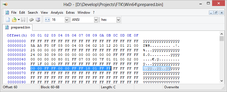
Keep these modifiers in the region descriptor at 0x60, and consist of three groups of 4 bytes.
The first group describes access to the region BIOS, the second region to ME, the third in the region GbE.
Details are available from
datasheet'a , paragraph 3.7.3.
We are interested in only the complete removal of protection, so that the sequence of bytes will be as follows:
00 00 FF FF 00 00 FF FF 18 01 FF FF.
Open the file that you are going to sew in Hex-editor and look at the selected line. If there is something different from the specified - correct.
Save the file as bios.bin and sew it using the
descrefl. After the restart protection will be removed from all regions.
------------------------------------------------------------
Ceci dit, il faut garder à l'esprit que cela concerne des CMs de PC Desktop!
cf aussi ici, où il est question de MàJ du FW ME en v8, qui délocke le FD et les régions:
https://www.overclock.net/t/1004219/official-asus-rog-maximus-iv-gene-z68-z68-gen3-owners-club/6370#post_18210519
To all, who has Error 26 on B3 boards: there are software flash lock that can be removed by flashing any ME 8 BIOS with EZ-Flash. So, flash last BIOS version and then you can use FTK to flash any other version, including ME 7 BIOSes without any errors.
I you have hardware SPI programmer, flash byte sequence "00 00 FF FF 00 00 FF FF 18 01 FF FF" beginning from 0x60 offset to remove that lock.
https://www.overclock.net/t/1345192/sabertooth-p67-i-7-3770k-overclock-help-3209-bios#post_18972445
This command can be used to see if your BIOS is locked by Region lock, because it will fail with Error 26 if any region is locked.
There are three methods of unlocking BIOS:
1. Powering the system on with GPIO line 33 pinned to GND with 1k resistor. Almost impossible on ASUS boards.
2. Using EZ flash to update BIOS from ME7 one to ME8 one. The ME update process after the first reboot will disable this lock. It is available only on relatively old boards.
3. Writing 00 00 FF FF 00 00 FF FF 18 01 FF FF to 0x60 offset of BIOS in SPI-chip with hardware programmer. The ultimate solution, but if you have hardware programmer, you don't need FTK anyway.
Now I am working on BIOS modification to prevent that lock from working, and I have some relatively good ideas of how to do that, but there is no actual code now, so you have to wait.
The output file of that command is called "backup.bin".
et là:
https://www.bios-mods.com/forum/Thread-UEFI-Dell-XPS-15z-L511z-modded-BIOS-and-HOWTO?pid=51306#pid51306
Error 26 means that your flash descritpor region is locked and therefore some regions of SPI have restricted access for writes and reads.
On boards with 6-series chipsets this problem can be solved by flashing a BIOS with embedded ME 8.xx (for Asus desktop boards these are BIOSes with version number 3xxx). After updating the BIOS flash descriptor will remain unlocked and those allow to write to all the other regions.
For the boards with series 7 chipsets such an error is a rare occurrence and in case of such boards updating the BIOS won't help. The only way to unlock flash descriptor for 7-series boards is by writing a sequence of 00 00 FF FF 00 00 FF FF 18 01 FF FF into address 0x60 using a hardware flasher/programmer.
NB: A savoir que sur le K53SV, plateforme HM65 (aka: Intel 6-series chipset), il semblerait que ce soit 1 version 7 de l'Intel ME qui soit installée. Vu avec FD44 Editor v0.85 et le fichier de dump du site 1Bios.ru:
------------------------------
Pour en revenir à ton problème, la raison pour laquelle j'avais besoin des dumps de tes 2 PCs, c'était pour comparer, avec ce que je possédais moi-même (il y a bien 1 différence sur les accès), et puis par comparaison entre le FD du K53SV et celui du X73E, le verrouillage pouvait expliquer la disparition de l'UUID et de la m@c: il semblerait que non (mais est-ce certain? est-ce que tu vois les 2 (UUID & m@c sur le X73E? quelle est l'adresse m@c (3 1ers octets?), puisque avec les mêmes restrictions, sur le 1er, c'est UUID+m@c = KO, sur le 2nd c'est OK.
Dc retour à ce que je te proposais, sans être absolument certain que ça passe.
Envoi-moi également le dump du BIOS de ton K53SV.